|
ABSTRACT
Engineered rock-faces involve evaluating the efficiency of rockfall mitigation measures e.g. rockfall dams. Existing rockfall models are not suited for this purpose because they do not account for the non-linear dynamics of rock motion, which is highly dependent on rock size, shape and impact configuration. Herein we discuss the application of the new 3-D rockfall modelling tool RAMMS::ROCKFALL which computes rock-ground interactions using hard-contact impact mechanics. The model is applied to evaluate the effectiveness of a rockfall dam at the GEOBRUGG test site in Walenstadt, Switzerland. At this testing facility, prototype flexible rockfall barriers are tested according to the European Standards (ETAG 027 guidelines) and Swiss guidelines. Recently the surrounding 150 m limestone rock-face became unstable releasing rockfalls which endangered the testing facility. In some cases falling rocks are launched from bench features causing the rocks to breach the dam causing obvious danger to operational staff and test site apparatus. We model the rock-face using a DEM with a spatial resolution of 0.25, which captures the relevant rock-wall topology that influences rockfall trajectory. We simulate scenarios with different rock sizes, shapes, starting orientations and release points. The simulated rockfall trajectories and the chosen risk reduction solution are presented.
1. INTRODUCTION
1.1 Rockfall hazard
Rockfall is a gravity driven natural hazard which threatens human infrastructure and settlements. One of the most recent rockfall events occurred in November 2015 along the main railway line between North and South Switzerland in Gurtnellen; and endangered a train carrying 190 people (see Fig. 1).
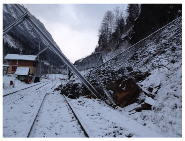
Figure 1. Rockfall event that occurred in November 2015 and impacted the main railwayline in Gurtnellen, Switzerland.
The incident can be seen in Figure 1 in which a rockfall barrier and catenary support were impacted by rock. The rockfall event exceeded the capacity of the rockfall barrier. It was a small rockslide with an estimated volume of around 100 m3 according to the Swiss railway geologists report.
In order to predict and design for rockfalls, advanced methods in rockfall modeling and barrier engineering are required. Over the past years there have been a number of advances that have resulted in a marked improvement in the state of rockfall engineering. The different types of improvement are described in the following sections.
1.1 Rockfall modelling
For many years 2-D modelling has been the state of the art to model rockfall problems. A number of different software is available on the market e.g. Rockfall (Spang & Sönser, 1995) and ROFMOD (Mohr, 2015). In these approaches it was very important to focus on the field survey. The selection of the correct slope profile for modeling is decisive in defining the maximum rockfall energies and bouncing heights. Ground conditions have to be chosen that are representative of the contacts and interactions between the rock and the slope.
In recent years 3-D modelling programs have become the new engineering standard in rockfall design. Initially the rockfall model has mostly been used for research purposes, but most recently also for commercial surveys of rockfall problems. Herein, we focus on 3-D modelling with RAMMS::ROCKFALL developed by the WSL, notably it applies a rigid-body approach (Leine et al. 2013).
1.2 Rockfall protection measures
Since the first rockfall guideline for flexible rockfall nets was developed (Gerber 2001), notable advances in rockfall barrier design have been made over recent years. Flexible protection nets are capable of withstanding rockfall impacts of up to 8,000 kJ since 2011, and are now nearly on same energy level as large protection dams (Fig. 2). Dams are able to contain up to 10,000 kJ, but require lots of space, and for steep terrain their foundations are nearly impossible to dimension for the required load transmission to the ground. Finally concrete rockfall galleries offer protection for higher energy rockfalls and are applied for railways and roads.
For lower energy levels up to max. 50 kJ, rigid fences like Jersey elements or timber barriers are an option. Special applications of flexible nets like flexible rockfall galleries, drapery systems, attenuator systems and slope stabilization are methods using flexible nets developed over the past 3 years.
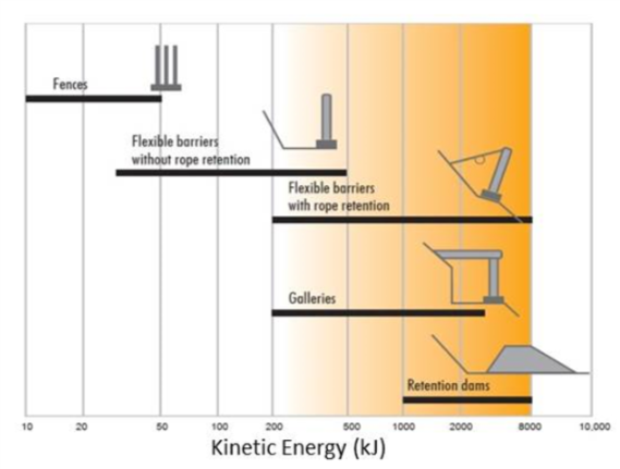
Figure 2. Overview of energy level of different rockfall protection methods up to 8,000 kJ.
1.1 Test site Walenstadt – endangered area
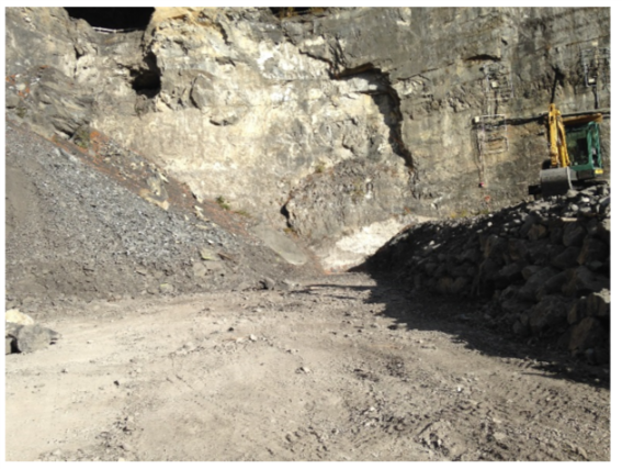
In 2000 this test site for flexible rockfall barriers was established by WSL together with Geobrugg. To date more than 200 development and certification tests have been performed there. The test site is an old quarry with limestone rock slopes in which over the past century blocks and gravel had been processed. Steep rock slopes larger than 150 m surround the test site.
On the eastern quarry wall foundations for rockfall barrier tests are installed above which is a crane capable of releasing blocks up to 20 tones with a falling height of around 40 m (see Figure 3). With these boundary conditions we are able to achieve impact energies up to 10,000 kJ.
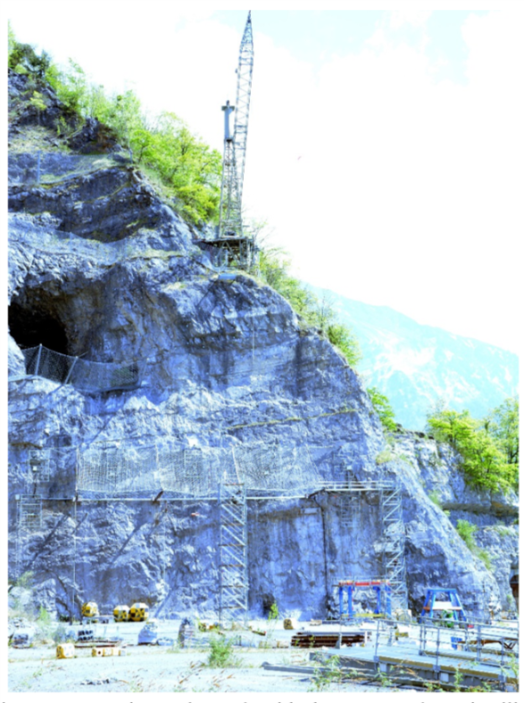
Figure 3. Test site Walenstadt with the crane and test instillation for flexible rockfall barrier testing.
The flanking cliff to the testing facility poses a rockfall hazard. Loose rock material lies on cliff benches in addition to weathered material in the rock-face. Past rockfall events were stopped by an artificially constructed dam with a large retention area behind. Over the years the retention area behind the dam has become filled (Fig. 4). Recent rockfall activity has exceeded the dam and runout has occurred into the testing facility where people are working. From the first onset of dangerous rockfalls it was clear that a reassessment of the hazard potential should be made and a method to enhance safety of the site be proposed.
The first decision was to clean out the retention area behind the dam. Initial works involved an excavator with a rock-breaker. However, the vibrations from these works triggered further rockfalls. Thus rock scaling works were performed on the rock-face to remove all small sized rocks. Larger rocks deemed as unstable were fitted with extensometers and monitored.
Additionally, a hazard analysis was performed by running rockfall simulations of the site. This marks one of the first field application for a mostly research based rockfall program RAMMS, in particular for such steep slopes. This work and the results are presented in the following section.
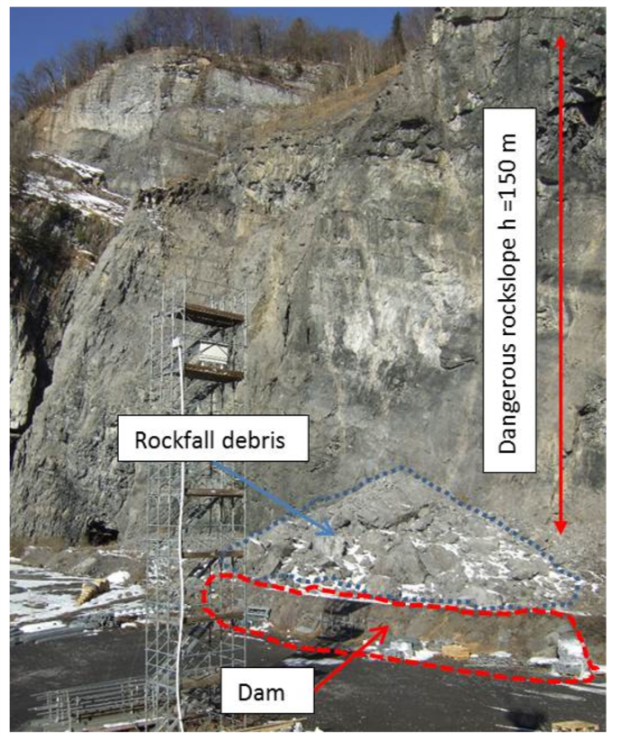
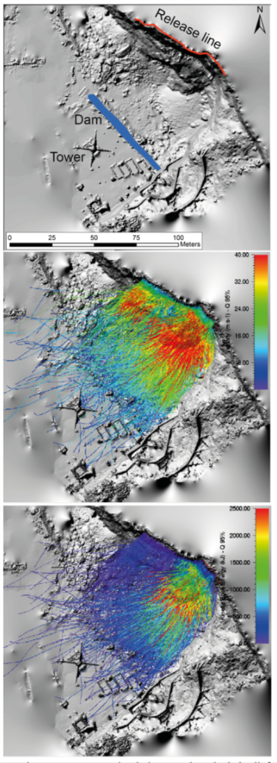
Figure 4. Hazard situation at analyzed slope with catchment area, completely filled up retention bassin and protection dam. In front the measurement tower of WSL which was also affected once by rockfall.
1.2 Hazard AnalySiS by 3D-Rockfall modeling
To assess the danger of rocks falling from the rock-face, we simulate rocks with equant form, considering this to represent a worst-case scenario. We acquired the terrestrial laser scan of the slope morphology with a Riegel VZ 6000 from three different scanner positions. The resulting digital elevation model DEM is a high-resolution (0.25 m pixel size) representation of the steep rock-face. It was not possible to capture areas above the rock-face and flat parts within the wall with the laser scanner. However, the main section of the rock-wall is well represented, and has facilitated meaningful numerical simulations.
We release rocks from 337 positions with 3 random orientations each with volumes of 0.1, 0.5, 1, 1.5 and 2 m3. In total this generates 5055 single trajectories to be simulated. The simulation results show that most rocks are contained by the dam. However, a small but significant portion of the rocks are able to exceed the dam, and run out into the area where people are working. These rocks hit the relatively flat flank in the wall and are deflected into the direction of the working area. It is only with the 3-D ridged body approach to rockfall modelling that it is possible to capture the detailed rockfall runout behavior that leads to rocks rolling up over the geometry of the retention dam. Moreover it is thanks to the high resolution terrain model of the specific hazard site that facilitates such modelling and allows the correct dimensioning of the required mitigation solution.
- Rockfall Mitigation Solution
The first step was to perform scaling work on the rock-slope to ensure safety during the required extraction of material from behind the dam within the catchment area. A larger unstable block was instrumented with an extensometer to monitor its movement.
In addition to the 3D simulation, the 2D simulation described in Mohr (2015) corroborates the recommendation of enlarging the dam to a capacity of 4 m height in order to reduce the risk of blocks exceeding the dam. Material from the catchment area behind the dam could be used to enlarge the dam (see Fig. 6).
Additional protection nets with a capacity of 500 kJ at the eastern part of the rock face have been installed to reduce the maximum energy of the blocks that fall onto this site. Without such protection measures the rocks would exceed the dam. Rockfall rebound jump heights in close proximity to the dam without protection nets are on the order of 25 m and would exceed the dam because it is too close to the rock face.
Conclusions
Within this problem case, albeit there a large number of rockfall protection measures available on the market, there was a direct need to assess the dynamics of the rockfall runout. This was particularly the case when considering the dimensions of the rockfall dam and catchment ditch to ensure full retention of the rockfall hazard. A large problem in this case was the potential for rocks to roll up over the retention dam posing a threat to the operators of the rockfall testing facility in Walenstadt.
|