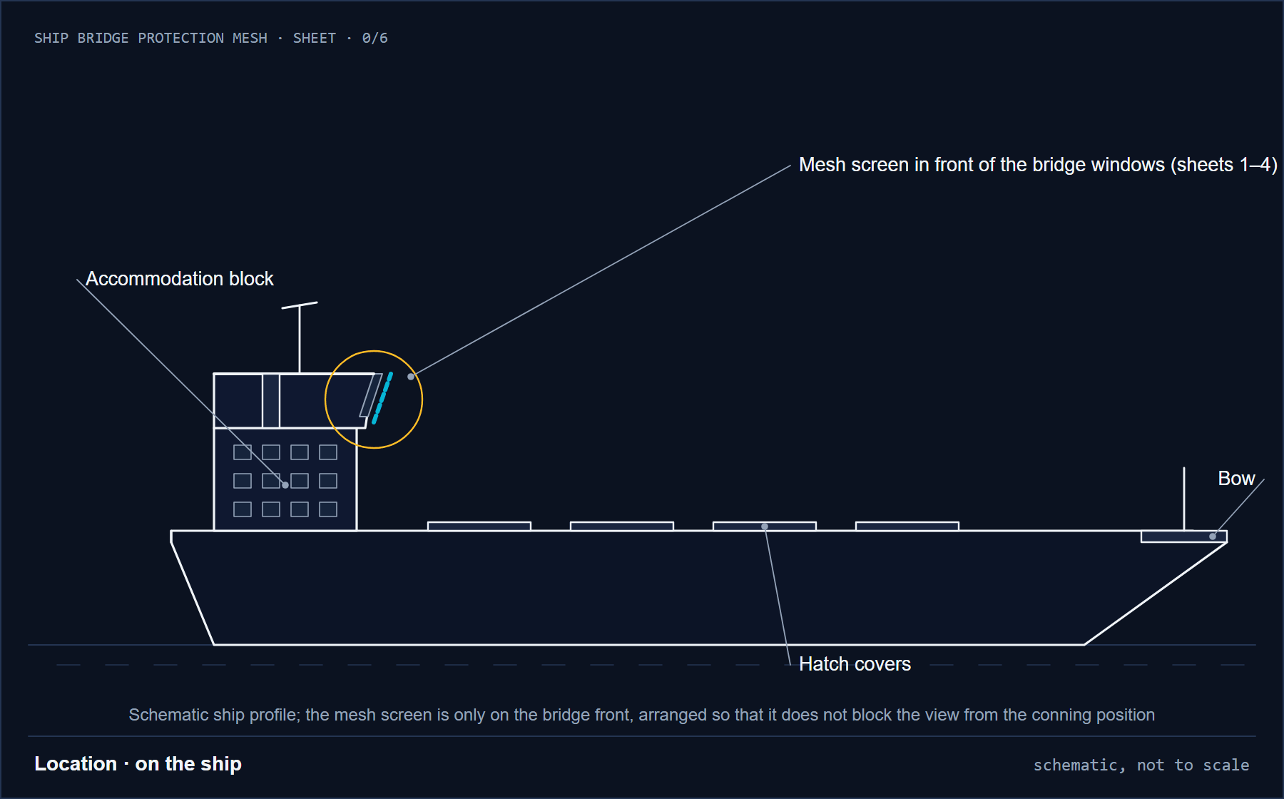
Framed stainless steel mesh panels in front of the bridge windows, at a set gap from the glass: protection against drones and flying debris without blocking the view from the conning position. The panels are hinged at the top and open for window cleaning; in normal service they stay open or are removed and are closed when entering high-risk waters. The connection is bolted or made with class-approved welding; acceptance of any element in front of the bridge windows rests with the flag Administration. The ship version of the protective cages built around tanks.
The problem
The bridge windows are the most exposed point of a ship: under way, the conning position is right behind the glass, and the glass is the first surface an object from outside hits. The protective cages built around the turrets of tanks are the answer to this question for a land vehicle; for the bridge, the same logic is built in front of the glass as a mesh screen that does not block the view. The threat is not of one kind, and each carries its own mass, speed and angle of impact:
| Threat | What it brings | What it decides in the design |
|---|---|---|
| Small unmanned aircraft (drone) | Small mass, high speed; body and propeller fragments | Mesh opening and the way the mesh absorbs energy |
| Storm and blast debris | Equipment thrown by wind, broken glass, ice | Area covered by the mesh and frame strength |
| Falling object | Parts dropped during crane and mast work | Closure from above; together with the roof visor |
An example for the scale of energy: an object of 10 kg arriving at 50 m/s carries a kinetic energy of ½ · m · v² = 12.5 kJ. This is not a design value but an order-of-magnitude reading. Which threat is treated with which mass and speed is defined during the survey; the mesh and frame are chosen accordingly and, where needed, proven by testing. No "stopping" value that has not been shown by a document is written on this page.
How we decide
The data we measure and compile: the geometry of the bridge front (number and size of windows, inclination top out), the position of window mullions and shell plating (where brackets can attach, stiffener lines), the field of view from the conning position, radar and antenna layout, service speed and prevailing wind (relative wind load), vibration, icing and salt-water washing, installation options in port (crane, scaffolding, permission to weld).
| Observation | Criterion | Decision |
|---|---|---|
| Small fragments and drone threat | Fragments must not pass through the mesh opening | Small-opening high-tensile mesh; a secondary fine mesh if needed |
| Field of view close to the SOLAS V/22 limit | Thin wire and sparse frame are essential | Thin wire (2 – 3 mm by product family: DELTAX 2 mm, TECCO G65/3 3 mm), frame aligned with the window mullions, panels divided to the window module |
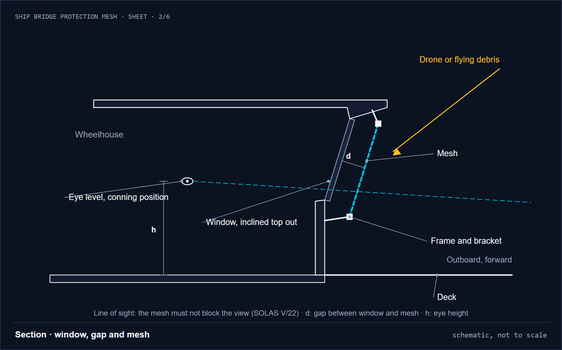
| Little room in front of the glass (visor, wipers, heaters) | The deflection of the mesh must not reach the glass | Gap d = expected deflection + margin; the frame is moved outward if needed |
| No welding to the hull wanted | No holes and no welding in the structure | Brackets bolted to the existing mullions and surrounding profiles; the addition is still notified to the classification society |
| Salt environment, frequent washing | High corrosivity (EN ISO 9223 category) | Stainless mesh and frame (316L or equivalent); dissimilar metals insulated |
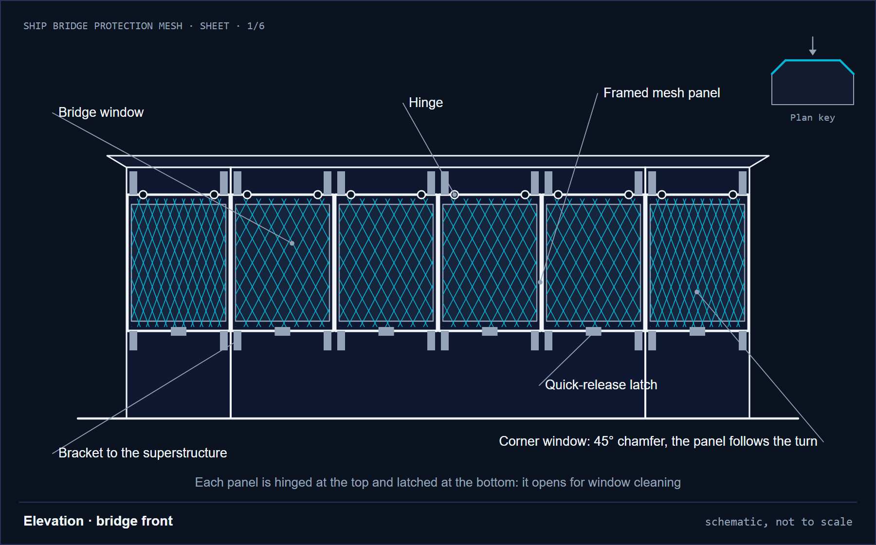
| Window cleaning and wiper access | The panel must open | Top hinge, quick-release latch at the bottom, safety lanyard |
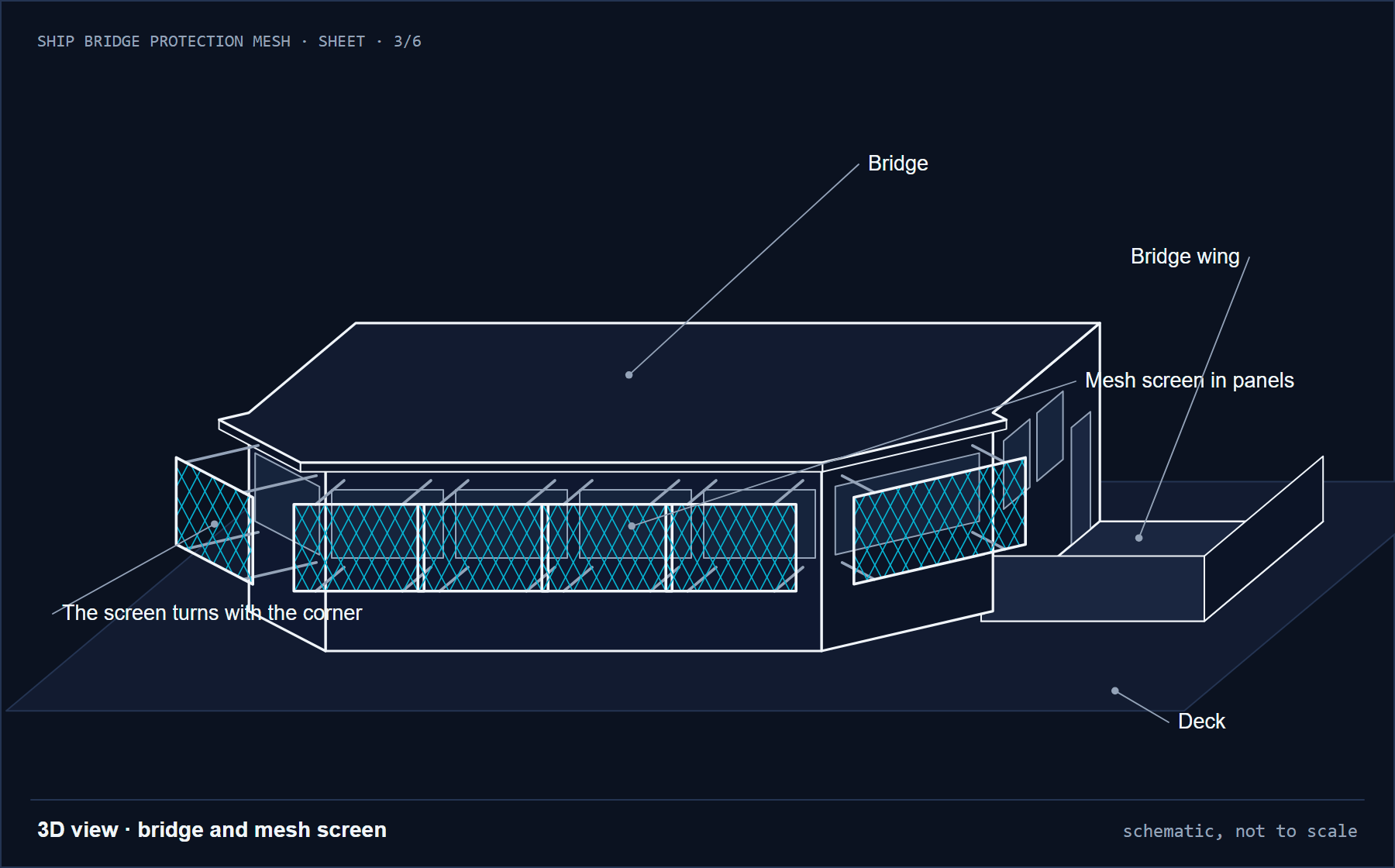
| Front chamfered at the corners (windows turn towards the wings) | Each face of the front is its own plane | One panel per face; the corner panel is measured and framed separately, no mullion is shared at the turn, each panel hangs on its own brackets |
| No permanent element wanted in front of the glass (SOLAS V/22, flag acceptance) | Windows free in normal service | Deployable system: panels open or are removed, the curtain is gathered up; at least two clear-view windows always free |
The system
| Component | What it does | Choice |
|---|---|---|
| Mesh | Holds the object; absorbs energy by deforming and transfers it to the frame | Stainless high-tensile steel wire mesh (Geobrugg TECCO G65/3 stainless or DELTAX); for large fragments a ring net panel from our own factory |
| Frame | Keeps the mesh tensioned, carries the load to the brackets | Stainless box section; panel size to the window module; mesh edge clipped to the frame |
| Gap d | So that the deflection of the mesh does not touch the glass | Parallel to the glass; deflection margin plus wiper and visor clearance |
| Hinge and latch | The panel opens for window cleaning and glass replacement, and stays open in normal service | Top hinge, two-point quick-release latch at the bottom; hold-open device and safety lanyard |
| Bracket | Connects the frame to the superstructure | Welded lug (class-approved welding procedure) or bolted to the existing mullions; with a vibration pad |
| Insulation and drainage | Prevents galvanic coupling and standing water | Insulating washers where stainless meets carbon steel; drain hole under the frame; electrical continuity as the project requires |
The mesh is chosen from Geobrugg's high-tensile steel wire mesh family; Artusa has been Geobrugg's representative in Türkiye since 2009. Ring net and frames are made in our own factory.
View and rules
Visibility from the bridge is governed by SOLAS Chapter V Regulation 22: the view of the sea surface and the horizon from the conning position, blind sectors, framing between windows kept to a minimum, and a clear view through at least two front windows at all times regardless of weather (paragraph 1.9.4). IMO's bridge design circular (MSC/Circ.982) foresees no permanent element in front of the windows; even sunscreens must be readily removable. For this reason the bridge mesh is described on this page not as a permanent structure but as a deployable protection: in normal service the panels are open or removed and the curtain is gathered up; they are closed when entering high-risk waters, in the logic of vessel hardening against piracy and drones. In every case at least two clear-view windows (wipers, washing, rotating clear-view screen) are left free or fitted with opening panels. Acceptance of any element in front of the bridge windows rests with the flag Administration; the classification society assesses the connection to the superstructure and the added weight, whether welded or bolted. This page makes no claim of "SOLAS compliance"; compliance is established with the ship's flag and bridge arrangement. The mesh does not cover the sectors of the navigation lights (COLREG Annex I), the whistle, wiper and washing access, the radar and antenna view, the pilot ladder and lifeboat areas.
Drawings
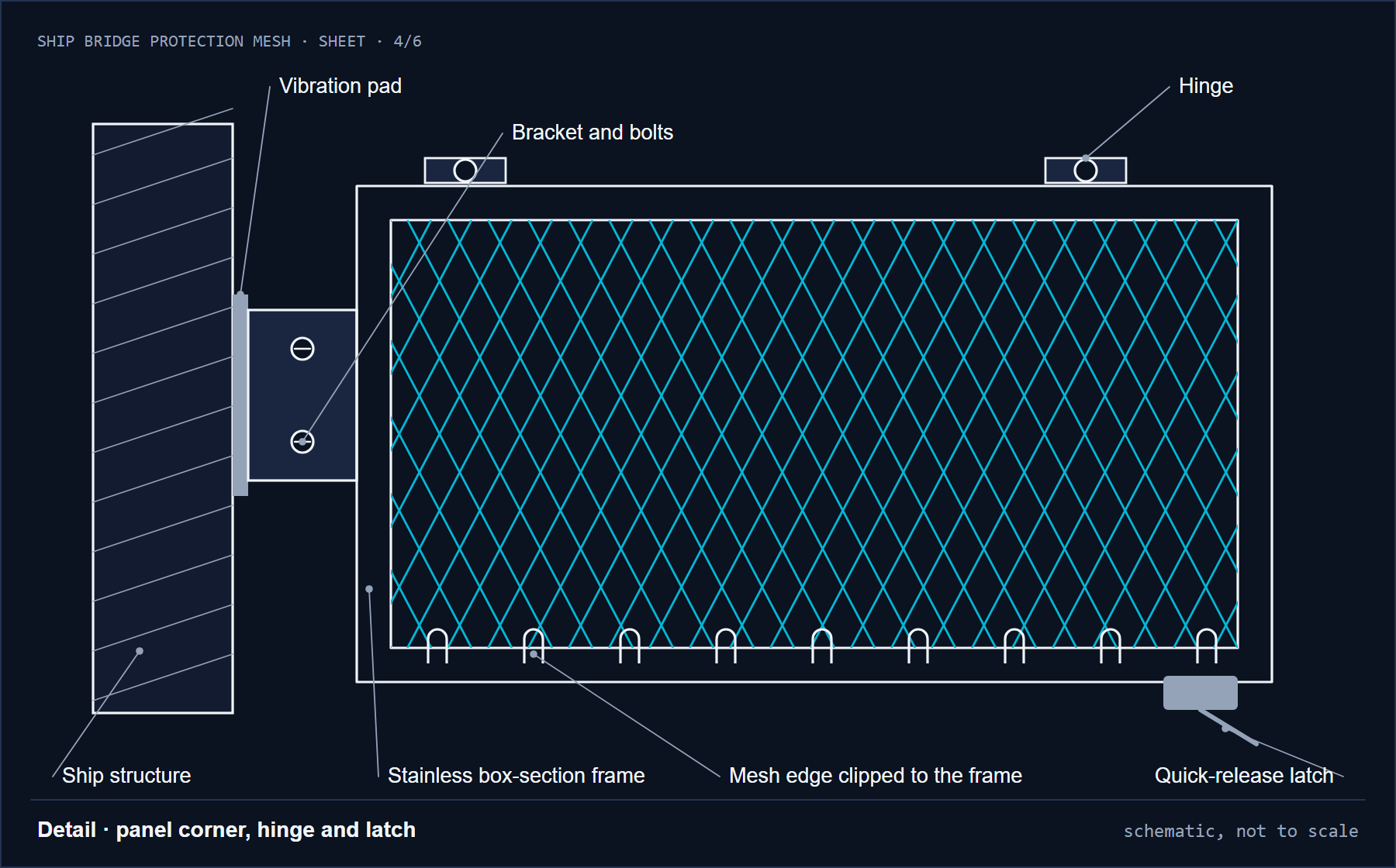
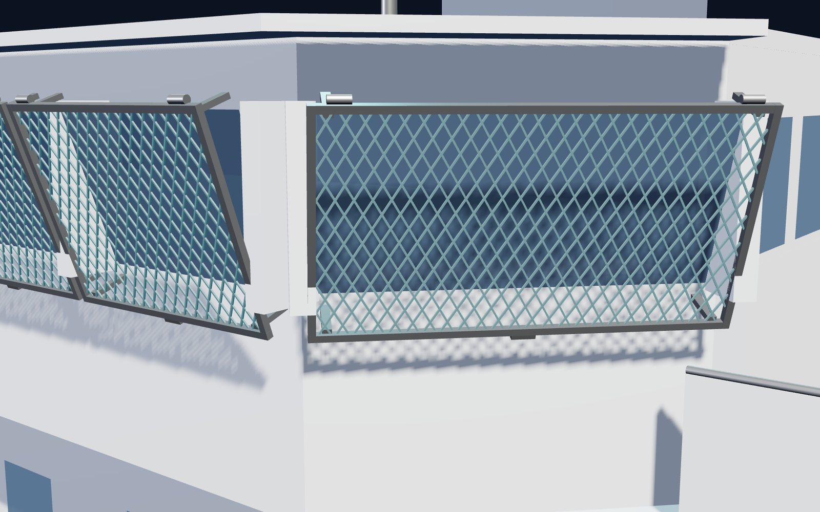
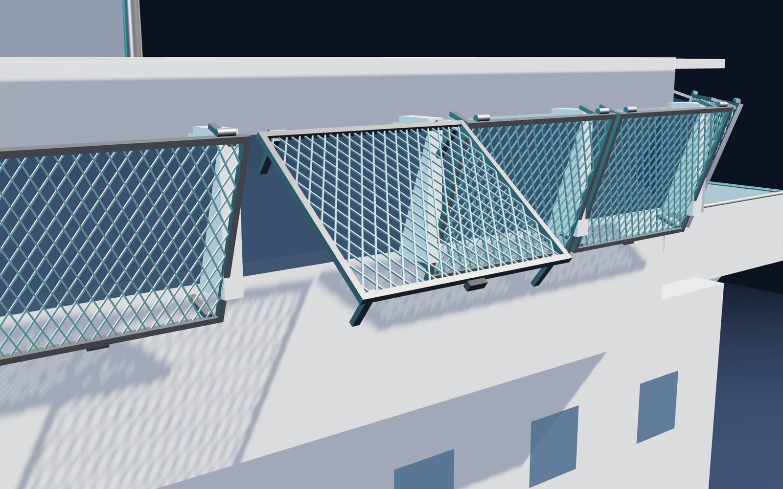
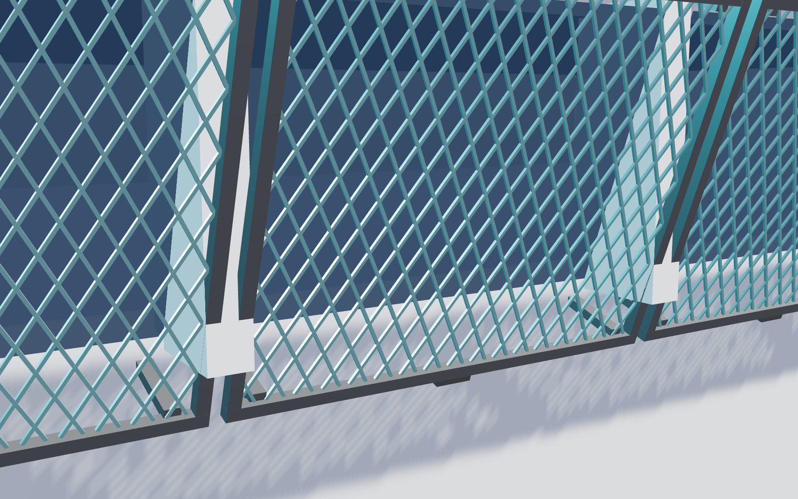
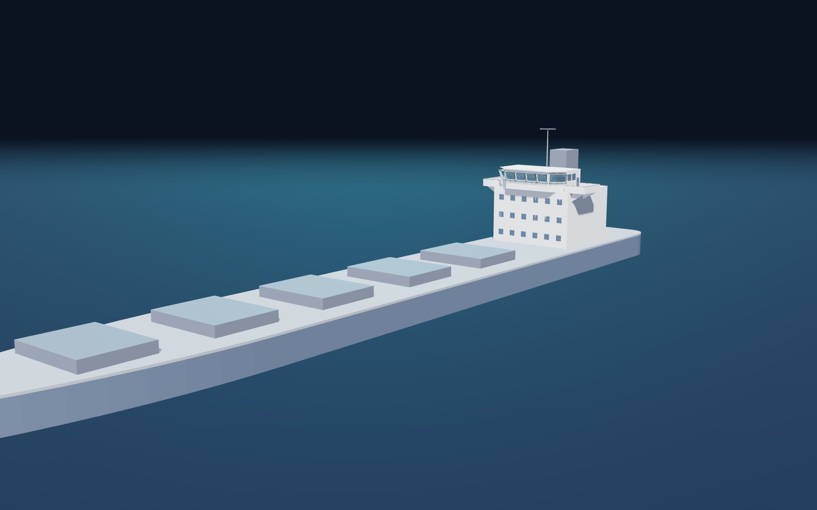
Two layouts: framed panel (A) and tensioned hanging curtain (B)
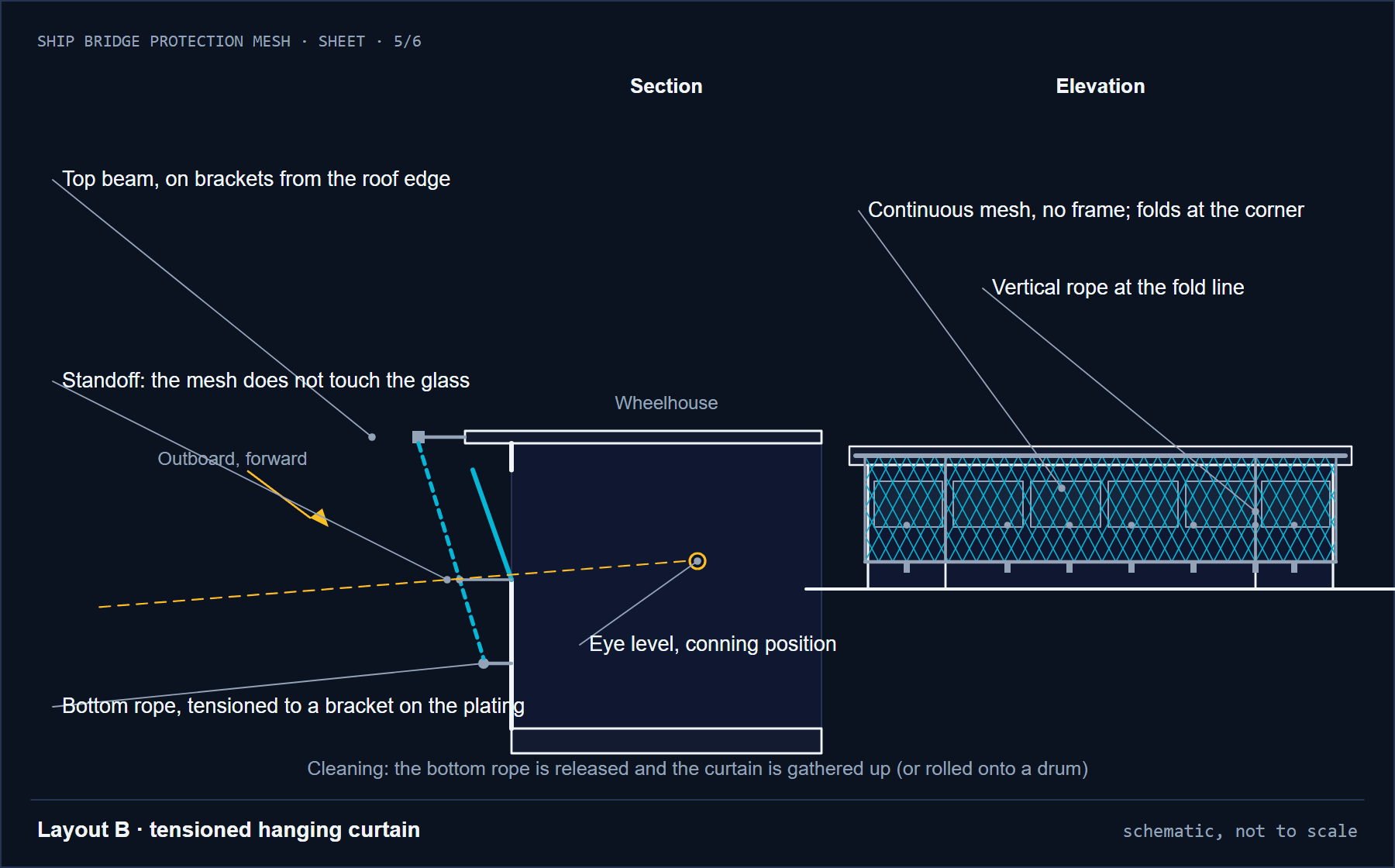
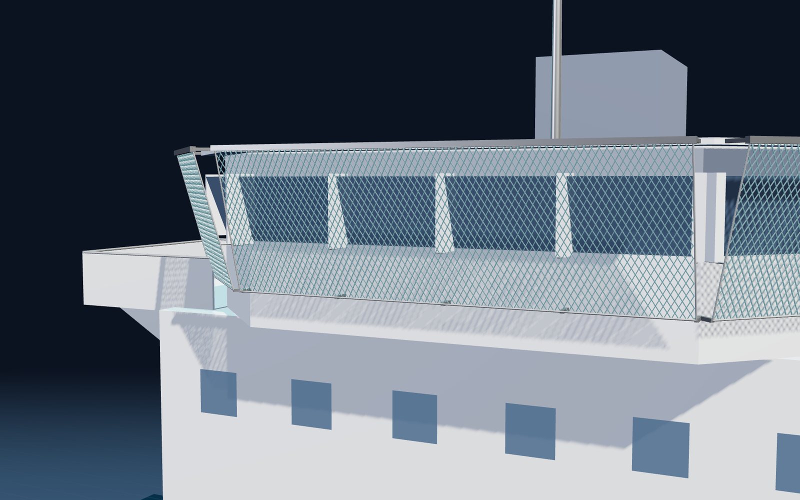
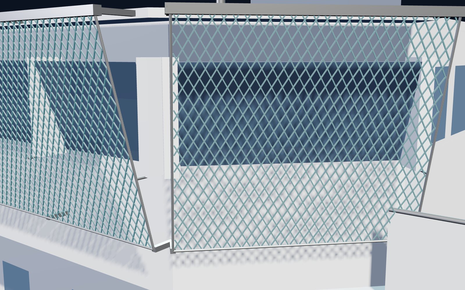
The same mesh can be hung in two ways. A — framed panel: panels divided to the window module, hinged at the top (sheets 1–4 above). B — tensioned hanging curtain: a continuous mesh tensioned from a top beam at the roof edge to a bottom rope on the plating below the windows; no frame, the corner is solved by the mesh folding at the break, with a vertical rope on the fold line. When the curtain hangs plumb, the top-out inclination of the windows opens the gap by itself: narrow at the brow, wide at the sill. The logic is that of the slope drapery and hanging-net systems we build on rock; the difference is that there is no surface behind the mesh, so the curtain is kept tensioned and held off the glass by standoffs.
| Criterion | A · framed panel | B · tensioned hanging curtain |
|---|---|---|
| Connection | Each panel on its own brackets; bolted to the window mullions | Top beam on the roof edge, bottom rope on brackets on the plating; no intermediate connection |
| Corner turn | The corner panel is measured and framed separately | The mesh folds at the break; vertical rope on the fold line |
| View | Frame sections stay in line with the mullions | No frame, only wire; edge ropes in line with the mullions |
| Deflection | Small, held by the frame; the gap d can be kept narrow | Larger, limited by tension; the gap is wider anyway |
| Wind | Rigid panel, little flutter | One large piece; needs close clips and standoffs |
| Window cleaning | The panel opens at the top | The bottom rope is released and the curtain gathered up; or rolled onto a drum |
| Doors, lights, wipers | Left free by the panel division | The curtain stops at the door line; cut-outs for lights and whistle |
| Where it fits | Bridges that want window-by-window maintenance, no welding, and stay with the module | Straight, high fronts with many windows, where fast installation and one-piece replacement are wanted |
Installation
Sequence: survey in port and measurement of the bridge front by laser scanning (window sizes, inclination, mullion positions); visibility check and panel division; frame and bracket design, class file if required; stainless fabrication and pre-assembly in the workshop; installation on board (bolted where possible, no welding), panel adjustment and latch check. Checkpoints: gap between glass and mesh, alignment of the frame with the mullions, bolt torque, latch and hinge function, hold-open safety, insulating washers, drainage.
Acceptance and maintenance
Measured at handover: visibility check from the conning position (by day and by night), as-built dimensions, material certificates (mesh, frame, fasteners), torque list, opening and closing test. Maintenance: fresh-water rinse after salt-water washing, lubrication of hinges and latches, check for crushing and broken wires in the mesh, torque of bracket bolts, traces of corrosion; panel replacement after a storm or an impact. Records go into the maintenance log; on request, a QR-coded tag is opened as on our land lines.
Frequently asked
- How much of the view does it block? With thin wire and a sparse frame the area covered by the mesh is small; the real criterion is the visibility check from the conning position under SOLAS V/22, done by day and by night at handover.
- Is welding required? No; brackets bolted to the existing mullions and surrounding profiles are preferred. If welded lugs are wanted, they are made with a class-approved welding procedure. In both cases the addition to the superstructure is notified to the classification society.
- Is it permanent? No. In normal service the panels are open or removed and the curtain is gathered up; the screen is closed when entering high-risk waters. Acceptance of any element in front of the bridge windows rests with the flag Administration; this page makes no claim of SOLAS compliance.
- Does it stop a drone? The mass and speed it is designed for are written down; performance is shown by testing. No value that has not been tested is given on this page.
- What is needed for a quotation? Photographs and dimensions of the bridge front, or a survey; the number of windows; which threat; whether welding is permitted; port and date. Request a quotation.
Sources: SOLAS Chapter V Regulation 22 (navigation bridge visibility); IMO MSC/Circ.982 (guidelines on ergonomic criteria for bridge equipment and layout); COLREG Annex I (positioning of lights); Geobrugg AG TECCO and DELTAX product information. Drawings and model are schematic and not to scale; the numerical design is made from the survey measurements.